
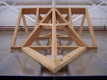
This image is working with a set plan. The blue lines indicate the walls that are hypothetically built and we know have to place a roof on top with one gable end and one hipped end. The pitches are given for each roof surface. From there we can draft a line on the gable end that is the span of the building (it is in blue). Since we are given the pitches for both A and C we can then draft the lines according to their pitch as rays from the blue line. (i.e. A is 12/12 also 45 degrees therefore if we measure the entire span from the A side of the blue line we then rise the same amount at the end of the line). The same can be done for C. Where these two rays meet is the ridge height of the roof and the placement in plan. We then do the same for B Elevation that is above the plan view in this drawing. We know where to stop this pitched slope line because we have just determined the ridge height. From there we bring that intersection down to plan and we can now place our hips.
**** Roof A and C need to be switched in drawing (pitches are misrepresented)
Hello Decatur,
ReplyDeleteI came here following a comment you placed on The Carpentry Way blog about the "french" descriptive geometry system. You said you were doing a course and that:
"We have graphically represented two pieces oriented at any angle that intersect."
This exercise interests me, especially if you can show how to take off the angles on the surfaces of the sticks where they cross (hope that's clear!).
Can you help me with this?
Rob